UPS Application vs. UPS Topology Selection: A Practical Matching Guide
Choosing a UPS by industry label is tempting: online for a data center, line-interactive for an office, standby for a workstation. Real systems are not that simple. UPS application vs. UPS topology selection is a requirements-matching exercise. The load’s tolerance, site power, downtime consequence, runtime target, and maintenance strategy should lead; topology follows.
|
Quick answer Start with the load and the site, not the topology name. Standby suits lower-criticality, transfer-tolerant loads on stable power. Line-interactive adds voltage regulation and often fits distributed IT and branch systems. Online double-conversion is the usual starting point for high-criticality loads, difficult input power, or a verified need for uninterrupted inverter output. Then specify redundancy, bypass, runtime, batteries, generator interaction, distribution, and service access—the topology alone cannot deliver availability. |
Application and Topology Are Different Decisions
An application describes what must remain powered and what happens if it stops. A topology describes how a UPS routes and converts power. IEC 62040-3 classifies UPS output performance as voltage- and frequency-dependent (VFD), voltage-independent (VI), or voltage- and frequency-independent (VFI). These categories commonly align with standby, line-interactive, and online designs, but marketing names are not a substitute for the manufacturer’s declared classification and test data.
The Three Common UPS Topologies
| Topology | Normal behavior | Practical starting point | Verify |
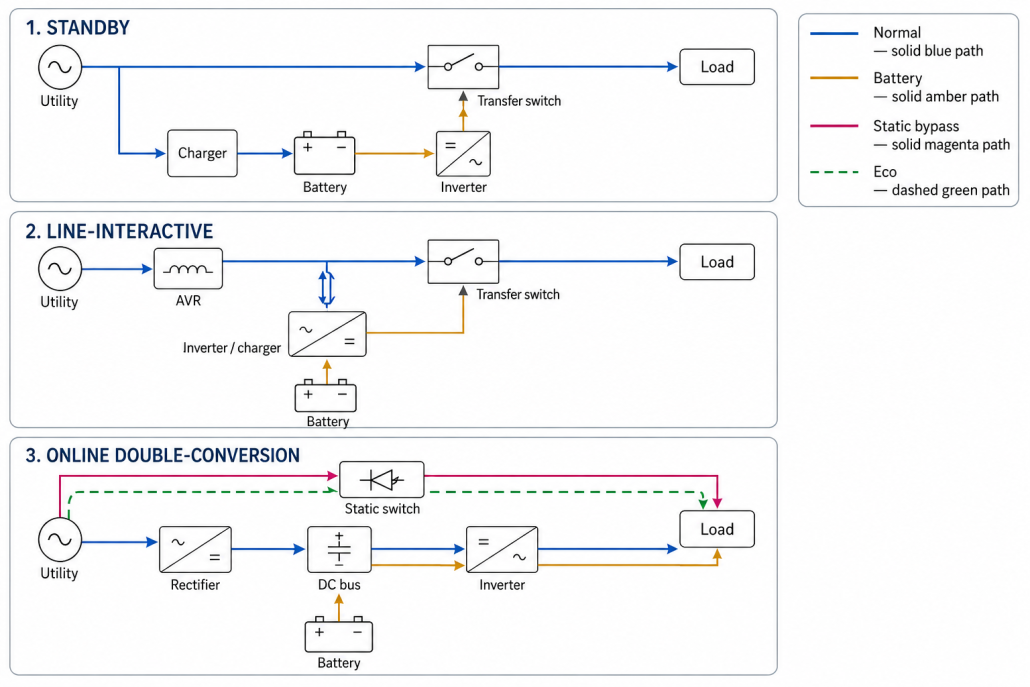
| Standby / offline | Acceptable utility normally feeds the load; the UPS transfers to its inverter when input leaves limits. | Basic electronics and lower-criticality loads on stable power. | Transfer time, battery-mode waveform, and input window are model-specific. |
| Line-interactive | Utility normally feeds the load; AVR corrects many sags or swells without battery use, then the UPS transfers when needed. | Network closets, branch IT, POS, security, and small servers when tolerance is verified. | It still has a transfer event and does not continuously regenerate frequency. |
| Online double-conversion | A rectifier and inverter continuously supply the load in normal double-conversion mode; the battery supports the DC bus during an outage. | Critical or sensitive loads, poor input power, and verified zero-transfer requirements. | Eco mode, static bypass, overload, and fault states use different paths. |
For mechanism-level detail, compare online UPS vs. offline UPS and standby UPS vs. line-interactive UPS. Do not publish a universal transfer-time number. Use the maximum value and test conditions from the exact model’s datasheet.
How to Choose UPS Topology in Five Steps
- Define the consequence of interruption. State whether the load can ride through a transfer, restart safely, or tolerate only an orderly shutdown. Include safety, lost transactions, corrupted work, process recovery, and customer impact.
- Characterize the load. Record continuous and peak kW and kVA, power factor, inrush, crest factor, harmonics, phase balance, waveform and frequency sensitivity, and any regenerative behavior. Motors, drives, transformers, imaging systems, and redundant power supplies need more than a nameplate watt total.
- Measure the source and site. Review outages, sags, swells, frequency variation, grounding, phase configuration, temperature, dust, altitude, acoustics, and generator behavior. A power-quality study is more useful than assumptions about the local grid.
- Design continuity and service. Set autonomy, generator-start allowance, N, N+1, or 2N redundancy, static and maintenance bypass, distribution, selective coordination, monitoring, service clearances, spares, and future growth.
- Validate the complete system. Compare product-level performance at the expected load and operating mode, then confirm load, generator, battery, BMS, protection, communications, enclosure, and approval compatibility with the responsible engineer and manufacturers.
Match the Starting Point to the Real Application
| Application | Starting point | What can change the answer |
| Home office / single workstation | Standby or line-interactive | Check active-PFC compatibility, waveform, transfer tolerance, shutdown software, and required runtime. |
| Retail, branch office, network closet | Often line-interactive | Move toward online when the source is unstable, loads are more critical, or generator/frequency behavior is difficult. |
| Server room / edge site | Line-interactive or online | Let storage, virtualization, restart cost, redundancy, maintenance, and site power determine the choice. |
| Data center | Usually VFI online at system level | Topology is only one layer; verify redundancy, bypass, distribution, generator, batteries, monitoring, and concurrent maintenance. |
| Telecom | DC plant or AC UPS, depending on the load | Many telecom systems use -48 VDC rectifiers and batteries. Do not insert an AC UPS where a DC architecture is required. |
| Healthcare | Application- and code-specific | Separate equipment categories and involve clinical engineering, the equipment OEM, and the responsible electrical professional. |
| Industrial automation | Often online for controls; special design for power loads | PLCs and instruments differ from motors, VFDs, welders, transformers, and regenerative loads. Verify inrush and overload behavior. |
These are screening positions, not prescriptions. A small but costly laboratory process may justify online power, while a resilient edge workload with dual power supplies and graceful failover may accept a different design. The failure consequence matters more than the room label.
Topology Cannot Solve the Whole Architecture
An online UPS can regulate output in double-conversion mode, but it cannot compensate for a poorly coordinated bypass, a single maintenance point, undersized distribution, incompatible generator, depleted battery, or missing monitoring. Static bypass supports defined overload or fault conditions; a separate maintenance bypass may permit service. Both change the power path and must appear in the one-line diagram and operating procedure.
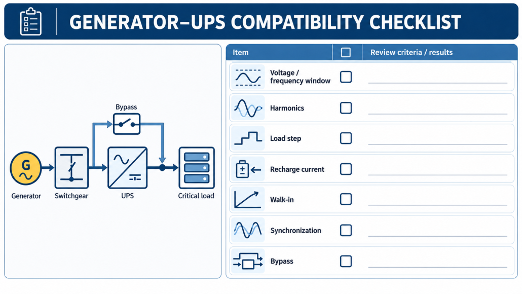
Generator compatibility also requires engineering. Review voltage and frequency windows, synchronization, alternator response to nonlinear load, rectifier walk-in, battery-recharge current, load steps, and return-to-source delay. An online label does not guarantee stable operation with every generator.
Runtime is a separate energy calculation. It depends on load, usable battery energy, conversion efficiency, discharge rate, temperature, age, and end voltage. Likewise, VRLA and lithium are separate architecture choices. A lithium system requires verified charger and DC-bus compatibility, BMS communications and protection, thermal design, enclosure integration, approvals, and warranty support; it is not a nominal-voltage drop-in swap.
Common Selection Mistakes
The most common mistakes are selecting by sector alone, comparing only VA ratings, treating every online operating mode as zero transfer, assuming topology sets runtime, ignoring bypass and maintenance states, and adding future growth without checking fault current or distribution. Another is using peak efficiency as a universal value. Compare efficiency at representative load, voltage, and operating mode, then include cooling, batteries, service, downtime, floor space, and generator impacts in lifecycle cost.
Frequently Asked Questions
Is online UPS always the best topology?
No. It offers strong conditioning and continuous inverter output in double-conversion mode, but it adds conversion losses, heat, cost, and complexity. Choose the least complex, fully compatible architecture that meets the verified continuity requirement.
Does online UPS always mean zero transfer time?
For loss of acceptable input while operating in normal double-conversion mode, the battery supports the existing DC bus and inverter path. Eco mode, static bypass, overload, faults, and maintenance states can behave differently, so verify every enabled mode.
Does UPS topology determine runtime?
No. Use the exact UPS and battery configuration’s runtime curve at the expected watt load, and account for temperature, age, discharge rate, efficiency, and the required end-of-life margin.
Final Recommendation
For UPS application vs. UPS topology selection, define the load, site, continuity objective, and service model first. Use topology as a controlled response to those requirements, then validate the full architecture under normal, battery, bypass, generator, fault, and maintenance conditions. That process produces a more reliable design than choosing a UPS from an industry label or a single specification.
For project teams evaluating the energy-storage layer, review LEOCH UPS battery solutions and discuss your UPS battery requirements by sharing the UPS DC voltage, load profile, target runtime, environment, communications, approvals, and service plan.