
Standby UPS Explained: How Offline UPS Systems Work and When to Use Them
Quick Answer: What Is a Standby UPS?
A standby UPS (also widely referred to as an offline UPS) is the most cost-effective and energy-efficient uninterruptible power supply topology. During normal electrical grid operation, the system routes utility AC power directly to connected equipment while maintaining an internal backup battery on continuous float charge. If the main power fails or utility voltage drops outside an acceptable threshold, an internal automatic transfer switch disconnects the utility grid and engages an inverter powered by the UPS battery.
With a typical switchover duration of 4 to 8 milliseconds, a standby offline ups provides seamless backup power for home offices, desktop computers, Wi-Fi routers, point-of-sale (POS) terminals, and small business networking equipment that can tolerate momentary transfer delays.
| System Specification | Standby UPS (Offline Standby UPS) |
| Alternative Terminology | Offline UPS / Standby Power Supply (SPS) |
| Typical Transfer Time | 4–8 ms (Milliseconds) |
| Output Waveform Mode | Simulated (Stepped) Sine Wave or Pure Sine Wave |
| Operating Efficiency | Very High (95%–99% under normal load) |
| Typical Capacity Range | 400 VA to 1,500 VA |
| Internal Battery Chemistry | VRLA (AGM) or Lithium Iron Phosphate (LiFePO₄) |
| Ideal Target Applications | PCs, Wi-Fi routers, CCTV cameras, POS terminals, IoT gateways |
How Does a Standby UPS Work?
The primary functional benefit of a standby ups system lies in its passive standby architecture. Under standard conditions, the inverter sits idle, eliminating constant power conversion losses and heat build-up.
Power Flow Architecture & Workflow
Mode 1: Normal Grid Operation
During standard utility conditions, raw grid power flows directly to the load while the battery charger tops off the backup cells.
Mode 2: Utility Power Failure or Outage
| Operational Phase | Power Path | Utility Grid State | Inverter Status | Battery Status |
| Mode 1: Normal Grid Operation | Utility Grid → Surge Filter → Transfer Switch → Connected Load | Active / Stable (Pass-through mode) | Standby (Idle) | Charging / Float |
| Step 1: Outage Trigger | Utility power drops or fluctuates outside acceptable threshold | Failed / Fault | Waking Up | Discharging Initiated |
| Step 2: Relay Transfer | Transfer Switch opens grid path and connects inverter path (4-8 ms) | Disconnected | Active | Supplying DC Power |
| Mode 2: Power Failure (Outage) | UPS Battery → Inverter → Transfer Switch → Connected Load | Offline | Active (DC to AC) | Discharging to Load |
Internal Power Switching Mechanics
Understanding the inner workings of an offline standby ups requires looking at five core internal sub-assemblies:
Inverter: The circuit responsible for converting direct current (DC) stored in the internal battery into alternating current (AC) suitable for connected devices during an outage.
Automatic Transfer Switch (Relay): An ultra-fast electromechanical or solid-state switch that constantly monitors utility voltage. When grid health fails, it physically transfers the load path from utility power to inverter output within milliseconds.
UPS Battery Assembly: The direct-current energy reservoir, utilizing either sealed lead-acid or modern lithium-ion chemistry.
Battery Charger: A low-wattage DC power supply that trickle-charges the battery during grid availability, keeping it at optimal State of Charge (SoC).
Surge Protection & EMI Filtering Unit: Suppresses high-voltage transients, line noise, and lightning spikes passing through the electrical outlet before they reach protected electronics.
Main Components of a Standby UPS System
Every offline ups is built around a streamlined set of internal sub-components engineered for reliability and long float life:
| Component | Primary Function in Standby Topology | Normal Grid State | Outage / Backup State |
| Surge Suppressor & Filter | Clamps high-voltage spikes and filters line noise | Active (Filters pass-through grid power) | Bypassed |
| Automatic Transfer Switch (ATS) | High-speed relay (4-8 ms) that swaps load source | Closed to Utility Grid | Switched to Inverter Circuit |
| Battery Charger | Low-wattage DC charger that preserves battery cell health | Active (Trickle/Float charging) | Idle |
| UPS Battery Assembly | DC energy reservoir (VRLA or LiFePO₄) | Float Charge / Standby | Discharging DC current |
| DC-to-AC Inverter | Converts direct current battery power into usable AC voltage | Idle / Off | Active (Generates AC output) |
How Component Integration Ensures Reliability
While individual sub-assemblies perform distinct tasks, their interaction is tightly governed by the main control board. Under normal conditions, the battery charger maintains a steady float charge on the VRLA or LiFePO₄ battery while the surge suppressor clamps incoming line transients. The instant utility voltage breaches threshold limits, the ATS triggers the DC-to-AC inverter. Because standard switch-mode power supplies (SMPS) feature a design hold-up time of 16-20 ms, the transfer switch’s 4-8 ms delay passes completely unnoticed by connected electronics.
Standby UPS vs. Line-Interactive UPS vs. Online UPS
Choosing the correct topology requires evaluating the trade-offs between standby vs line interactive ups and online double-conversion architectures. Each topology handles power quality, voltage stabilization, and battery engagement differently.
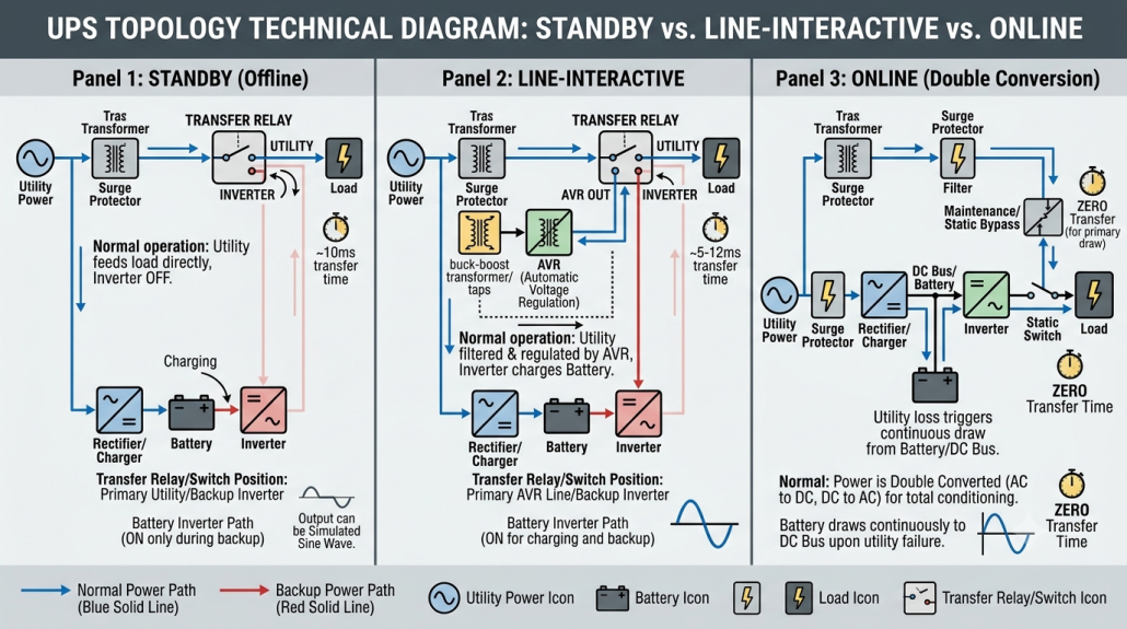
Topology Comparison Matrix
| Technical Feature | Standby UPS (Offline) | Line-Interactive UPS | Online UPS (Double-Conversion) |
| Typical Transfer Time | 4–8 ms | 2–4 ms | 0 ms (Seamless Continuous Path) |
| Voltage Regulation | None (Pass-through utility) | Automatic Voltage Regulation (AVR) | Continuous AC-DC-AC Conversion |
| Power Conversion Mode | Direct Grid (Inverter Standby) | Grid + Buck/Boost Auto-Transformer | Continuous Double Conversion |
| Output Waveform | Simulated or Pure Sine Wave | Pure or Simulated Sine Wave | Always Pure Sine Wave |
| System Efficiency | Highest (95%–99%) | High (96%–98%) | Moderate to High (90%–95%) |
| Thermal Output | Negligible | Low | Moderate to High |
| Relative Capital Cost | Lowest | Moderate | Highest |
| Battery Wear Rate | Minimal (Only during full outages) | Moderate (Cycles during voltage sags) | Continuous float / DC link integration |
| Ideal Deployment | Desktop PCs, routers, POS, CCTV | Workstations, SMB servers, switches | Mission-critical servers, medical, industrial |
Key Differences Explained
When evaluating line interactive ups vs standby ups, the major technical differentiator is Automatic Voltage Regulation (AVR).
A standby offline ups does not adjust incoming voltage fluctuations; if grid voltage drops to 102V AC, it simply passes 102V AC straight through to the load. If the voltage drops too low, it switches entirely to battery power.
Conversely, a line-interactive UPS uses a variable-ratio transformer to “boost” low voltages or “buck” high voltages back to normal operating ranges without draining the battery.
For environments with frequent brownouts or unstable grid power, line-interactive units preserve battery life. However, for stable municipal grids, a standby UPS offers better efficiency and lower upfront equipment costs.
Advantages of Standby UPS Systems
The widespread adoption of offline standby ups equipment across residential and commercial sectors is driven by several key engineering benefits:
Exceptional Energy Efficiency: Because power flows directly from the grid to connected equipment without active double-conversion, standby systems achieve up to 99% operating efficiency, minimizing electric utility costs.
Unmatched Cost Efficiency: Featuring simpler circuit topologies and fewer power conversion components, standby systems are substantially more affordable than line-interactive or online alternatives.
Silent and Compact Design: Passive cooling and idle inverter modes allow standby UPS units to run quietly without noisy cooling fans, making them ideal for home desks and quiet office environments.
Reduced Heat Generation: Minimal power conversion loss keeps operating temperatures low, extending the lifespan of internal electronics and battery cells.
Limitations of Standby UPS Systems
While cost-effective, standby systems are intentionally designed for non-critical electrical loads. Understanding their engineering limitations prevents costly network downtime:
Important Deployment Warning: Standby UPS units are not recommended for mission-critical IT infrastructure, industrial automation controllers, or life-support medical devices due to transfer time gaps and lack of active voltage regulation.
Transfer Time Delay (4–8 ms): Extremely sensitive electronics, medical monitors, or specialized industrial Programmable Logic Controllers (PLCs) may detect this momentary voltage gap and reboot.
No Active Voltage Conditioning: Severe brownouts, overvoltage surges, or dirty generator output are passed directly to the connected equipment until the UPS triggers a full switch over to battery power.
Waveform Limitations: Budget standby models produce a stepped or simulated sine wave when operating on battery. While fine for standard computer power supplies, simulated sine waves can cause electrical hum or overheating in active PFC power supplies, induction motors, and delicate audio gear.
Engineering Tip: Portable Generator Compatibility
Standby UPS systems require stable grid frequency (60 Hz ± 1 Hz). Because budget portable fuel generators suffer from engine speed fluctuations and frequency drift, a standby UPS may repeatedly switch between utility and battery power (known as relay chatter). If backing up power from a non-inverter generator, deploy a Line-Interactive UPS with wide frequency tolerance or an Online Double-Conversion UPS
Common Applications of Standby UPS
Matching the right load type to an offline ups ensures reliable backup power without overspending on enterprise-grade hardware.
| Industry / Environment | Target Equipment | Primary Threat Protected | Why Standby Topology Fits |
| Home Office & Workstations | Desktop PCs, monitors, Wi-Fi 6/7 routers, fiber modems | Brief blackouts, momentary sags | Power supply hold-up time easily absorbs 4-8 ms transfer delay. |
| Retail & Point-of-Sale (POS) | Cash registers, card terminals, receipt printers, scanners | Voltage drops during transaction processing | Low cost, compact footprint fits under tight sales counters. |
| Security & Surveillance | CCTV cameras, NVR/DVR recorders, access control panels | Intentionally or accidentally cut utility lines | Keeps continuous security recording active during power disruptions. |
| Small Business IT | VoIP phones, desktop network switches, edge IoT gateways | Loss of internet connection and dropped calls | High power efficiency (95%-99%) keeps utility bills low. |
Industry Application Breakdown
Home Office & Residential Networking: Desktop computers, Wi-Fi 6/7 routers, fiber ONTs, and NAS storage units. The 4–8 ms transfer time easily falls within the ride-through hold-up time of standard switch-mode power supplies.
Retail & Point-of-Sale (POS): Electronic cash registers, credit card processing terminals, and receipt printers. Keeps checkout lanes functional during brief outages.
Security & Surveillance Infrastructure: CCTV camera power distribution boxes, Network Video Recorders (NVRs), and electronic door access controllers.
Small Business Communications: IP phones (VoIP), desktop switches, and edge IoT hubs that require simple, compact emergency power.
Choosing the Right Battery for a Standby UPS
The performance and long-term operating cost of any UPS rely directly on its internal UPS battery. Historically, lead-acid batteries were the standard option, but advances in lithium technology have made Lithium Iron Phosphate (LiFePO₄) the preferred choice for long-term reliability.
VRLA (AGM) vs. LiFePO₄ Battery Technology
Sealed Lead-Acid (VRLA AGM)
Traditional VRLA AGM batteries feature a low upfront cost and mature manufacturing standards. However, they suffer from a short 3-to-5-year service life, heavy weight, and high sensitivity to ambient heat.
Lithium Iron Phosphate (LiFePO₄)
Industrial-grade batteries like those engineered by LEOCH Battery, a US lithium manufacturer, bring high cycle life and thermal stability to standby power applications. LiFePO₄ batteries deliver up to 10–15 years of floating service life, weigh up to 60% less, and recharge in a fraction of the time required by lead-acid cells.
Battery Parameter Comparison Matrix
| Performance Parameter | VRLA (AGM Lead-Acid) | LiFePO4 (Lithium Iron Phosphate) |
| Float Design Life | 3–5 Years | 10–15 Years |
| Deep Discharge Cycle Life (80% DoD) | 300–500 Cycles | 3,000–6,000 Cycles |
| Routine Maintenance | Minimal (Sealed) | Zero Maintenance |
| Weight Savings | Heavy (Baseline) | 40%–60% Lighter |
| Recharge Time to 90% | 6–10 Hours | 2–4 Hours |
| High Temperature Tolerance | Degrades quickly above 25°C | Excellent stability up to 45°C–50°C |
| 10-Year Total Cost of Ownership (TCO) | Higher (Requires 2–3 battery swaps) | Significantly Lower (Zero swaps needed) |
How to Choose the Right Standby UPS
Selecting the ideal standby ups system involves evaluating load capacity, appliance tolerance, and runtime requirements.
Capacity Decision Tree
| Equipment Setup | Recommended VA Range | Minimum Wattage Headroom | Ideal Battery Target |
|
Basic Networking
(Modem, Wi-Fi Router, Fiber ONT) |
400 VA – 450 VA | 100 W-150 W | Ultra-compact VRLA or LiFePO4 |
|
Standard Desktop PC
(Single Monitor + Mini PC / Office Desktop) |
500 VA – 650 VA | 250 W-350 W | Standard 650VA Standby Unit |
|
Home Office Workstation
(Dual Monitors + Desktop PC + Router + NAS) |
750 VA – 1,000 VA | 450 W-600 W | Mid-capacity Standby / Line-Interactive |
|
High-End Gaming PC / NAS
(Active PFC Power Supply + Multiple Drives) |
1,000 VA – 1,500 VA | 700 W-900 W | Pure Sine Wave Standby Unit |
| Critical Server / Medical Device | Do Not Use Standby | N/A | Switch to Online Double-Conversion UPS (0 ms Transfer) |
3-Step Sizing Guide
- Calculate Total Wattage Load: Add up the rated wattage of all devices you intend to connect. For example: Desktop PC (250W) + LED Monitor (35W) + Wi-Fi Router (15W) = 300 Watts.
- Convert Watts to Volt-Amps (VA): Most modern electronics operate with a Power Factor (PF) between 0.6 and 0.7. Divide your total watts by the power factor to get the required VA rating:
Target VA = Total Watts/Power Factor = 300W/0.6 = 500 VA
- Include a 25% Power Margin: Add a 25% buffer for future equipment additions or power surges. A 500 VA load requirement multiplied by 1.25 equals 625 VA. In this scenario, selecting a 650 VA or 750 VA standby UPS provides optimal headroom and extended emergency runtime.
Frequently Asked Questions
What is the difference between a standby UPS and an offline UPS?
There is no technical difference between them. “Standby UPS” and “offline UPS” are two names for the same topology, where the inverter remains idle on standby until utility grid power drops out.
Is a standby UPS safe for gaming PCs and workstations?
Yes, provided the UPS outputs a Pure Sine Wave. Modern gaming PCs and workstations use power supplies equipped with Active Power Factor Correction (APFC). When switching to battery power, budget standby units with simulated (stepped) sine waves can trigger APFC protection circuits, causing sudden system reboots or PSU strain. For APFC systems, choose a pure sine wave standby or line-interactive UPS rated for 1,000 VA-1,500 VA.
How long does a standby UPS last?
A standby UPS chassis typically lasts 8 to 12 years. However, internal battery lifespan varies by chemistry. Standard VRLA lead-acid batteries require replacement every 3 to 5 years, while modern LiFePO₄ lithium batteries last 8 to 15 years before needing replacement.
Does a standby UPS regulate output voltage?
No. A standby UPS passes utility voltage directly through to connected devices without automatic voltage regulation (AVR). If grid voltage drops or spikes slightly, the UPS continues passing utility power until the voltage breaches set threshold limits, at which point it switches to battery mode.
Can a standby UPS use lithium batteries?
Yes. Modern UPS systems are increasingly built with or upgraded to Lithium Iron Phosphate (LiFePO₄) batteries. Lithium cells provide longer service life, faster recharge times, lower weight, and zero routine maintenance compared to traditional lead-acid units.