Telecom Power Supply Buying Guide: Select the Right DC System
|
Quick answer A telecom power supply is the complete DC power chain, not the battery alone. Select it by the site’s peak DC load, required battery-recharge rate, autonomy target, input-source reliability, redundancy objective, battery and load voltage windows, distribution and protection, environmental limits, monitoring interfaces, and applicable U.S. or carrier requirements. Compare bids against defined operating conditions and acceptance tests—not headline watts, amp-hours, or efficiency alone. |
Telecom sites range from small outdoor cabinets to central offices and remote hybrid-power installations. Begin with the load and operating requirement, then work outward to rectifiers, batteries, distribution, controls, protection, and lifecycle support.
What Is a Telecom Power Supply System?
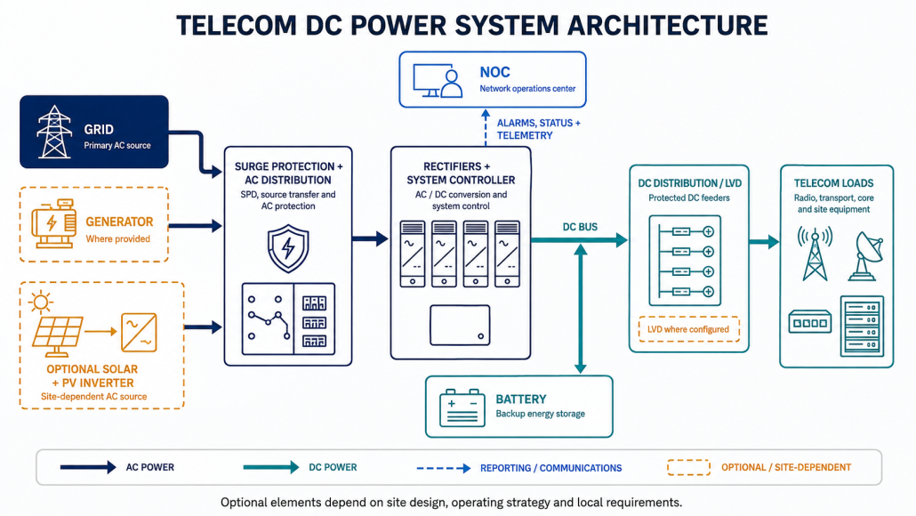
A typical system accepts utility, generator, or another AC source; applies input protection and AC distribution; converts AC to DC through rectifiers; and feeds the network load through a controlled DC bus and protected distribution. Batteries connect to that bus to support the load when input power is unavailable. A controller supervises rectifiers, batteries, low-voltage disconnects (LVDs), alarms, and communication with the network operations center (NOC). Remote sites may also include solar and dedicated hybrid-power controls. For a focused explanation of the battery’s continuity role, see how telecom battery backup works.
Many telecom plants are described as nominal -48 V DC. That convention does not make every ‘48 V’ or ‘51.2 V’ component interchangeable. Procurement must state polarity and return arrangement, normal and allowable DC-bus range, charging limits, load tolerance, disconnect thresholds, and the voltage seen during recharge and discharge.
Start With the Site and Operating Requirement
Document the site class, critical and deferrable loads, peak and average DC demand, expected growth, utility quality, generator availability, solar contribution, maintenance access, ambient conditions, and service-continuity objective. Required autonomy should come from the owner’s risk model, outage history, response time, generator start and fuel plan, carrier standard, and customer commitments—not a universal two- or four-hour rule.
| Site class | Selection emphasis |
| Core or central office | Emphasize distribution paths, maintainability, selectivity, alarm integration, room conditions, and documented redundancy. |
| Macro cell | Balance shelter limits, generator strategy, surge/lightning exposure, runtime, access, and growth. |
| Small cell or edge | Verify thermal behavior, service access, noise, enclosure rating, and remote visibility. |
| Remote or hybrid site | Model solar/generator energy, weather, fuel logistics, autonomy, controls, security, and extended-outage recovery. |
Size Rectifiers and Battery Runtime Separately
For the DC plant, begin with peak coincident load—not only the sum of equipment nameplates. Add the permitted battery-recharge current and a documented growth allowance to obtain the required active rectifier capacity. Then apply the redundancy objective so the plant can meet the defined duty after the designated module or path is unavailable. Verify that AC input, shelf, busbar, breakers, conductors, ventilation, and controller capacity support the result.
|
Conceptual rectifier-capacity method Required active capacity = peak DC load + approved battery-recharge allowance + documented growth allowance. Add redundancy only after defining which failure or maintenance condition the system must withstand. |
Battery runtime requires a different calculation. Use the actual load at the DC measurement point, allowable end voltage, temperature, aging allowance, discharge behavior, approved state-of-charge window or depth of discharge, conversion and auxiliary losses, and the generator or solar recovery plan. Amp-hours alone cannot establish runtime. The recharge setting also matters: an aggressive current may exceed battery, cabling, rectifier, thermal, or input limits, while a conservative setting extends recovery time.
Verify Battery and DC-Plant Compatibility
A lithium battery is not automatically a drop-in replacement for VRLA because both are marketed for 48 V telecom use. Confirm the full operating and charge window, current limits, LVD and reconnect settings, precharge or inrush behavior, hardware protections, fault response, rack and cable interfaces, parallel limits, environmental controls, and warranty conditions.
For lithium systems, verify how the BMS communicates alarms, state of charge, state of health, current limits, and contactor status. A label such as RS485, CAN, Modbus, or SNMP does not prove interoperability; both devices must support the same physical interface, protocol version, register or MIB map, scaling, alarm logic, and approved firmware. Review current LEOCH options only after the plant requirements are defined. See the separate guide to select a telecom battery system and confirm exact model data on the relevant product page.
Engineer Distribution, Protection, and the Site Environment
Check busbar ratings, feeder breakers or fuses, interrupting ratings, conductor ampacity and voltage drop, protective-device coordination, grounding and bonding, surge protection, lightning exposure, labeling, service isolation, and LVD segmentation. A battery or rectifier with a high fault-current capability can change the protection study. A common bus or controller can also defeat module-level redundancy if it remains a single point of failure.
Environmental review should include temperature, humidity, altitude, dust, salt, flood exposure, ventilation, heat rejection, seismic or wind requirements where applicable, access control, clearances, lifting paths, and service space. An enclosure IP rating addresses defined ingress tests; it does not establish thermal performance, corrosion resistance, flood suitability, or site reliability.
Specify Monitoring, Interoperability, and Cybersecurity
Define which measurements and alarms must reach the NOC: input failure, rectifier status and load sharing, DC-bus voltage and current, battery current and available battery data, temperature, LVD state, branch or breaker alarms, generator or solar state, and communication loss. Map alarm names, severity, delay, clear behavior, escalation owner, and acceptance test.
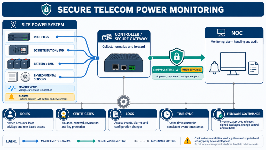
Where supported, prefer authenticated and encrypted management such as SNMPv3 or HTTPS over default or legacy configurations. Specify role-based access, unique credentials, certificate and key handling, time synchronization, logs, configuration backup, firmware support, vulnerability response, remote-access approval, and change control. Remote visibility can improve troubleshooting, but it reduces site visits only when alarms are accurate and the operations workflow acts on them.
Apply U.S. and Carrier Requirements to the Exact Project
Requirements depend on product scope, jurisdiction, facility, and buyer. Applicable ICT power equipment may be evaluated to UL/IEC 62368-1. A stationary battery may need evidence to UL 1973 when specified. Installation must follow the locally adopted electrical, building, and fire requirements; NEC battery provisions, including Article 480 where applicable, should be confirmed with the authority having jurisdiction (AHJ). Carrier procurements may require current Telcordia/NEBS environmental and electrical criteria such as GR-63-CORE and GR-1089-CORE, but NEBS is not a universal legal requirement.
For VRLA installations, IEEE 1188-2025 provides current recommended practices for maintenance, testing, and replacement. Always verify the exact product model, configuration, certification or listing record, report scope, code edition, carrier document revision, insurer conditions, and AHJ acceptance. At end of life, commercial lithium batteries require an approved recycling or waste path; federal and state rules can differ.
Compare Bids by Evidence and Acceptance Criteria
Ask every supplier to respond to the same load profile, input conditions, ambient range, autonomy method, redundancy case, and measurement boundary. Compare rectifier efficiency across the expected load curve, thermal derating, battery usable energy and warranty, controller and monitoring licenses, cybersecurity support, spares, field service, shipping, installation scope, commissioning, training, documentation, and end-of-life responsibilities. ‘High efficiency,’ ‘long life,’ and ‘future-ready’ are not specifications until the conditions and remedy are written.
Commission Before the Site Depends on It
Acceptance should cover inspection, torque and labeling records, polarity and grounding, breaker and LVD settings, rectifier sharing, module-loss behavior, alarms and NOC mapping, battery communication, an approved capacity method, generator or solar interfaces, configuration backup, and as-built documentation. Record the test point, conditions, pass criteria, result, exception owner, and closure date.
Frequently Asked Questions
Is a telecom power supply 48 V or -48 V?
Telecom plants are commonly described as nominal -48 V DC, reflecting the polarity and grounding convention. Equipment may also use ‘48 V’ as a nominal class, while a lithium battery may show a 51.2 V nominal nameplate. Compatibility depends on the complete operating and charging window, return arrangement, protection, and settings—not the label alone.
How many rectifier modules does a telecom site need?
Determine the active capacity needed for peak load, approved recharge current, and growth; divide by the usable module rating at the site conditions; then add modules required by the defined redundancy case. Also check shelves, AC feeds, busbars, distribution, cooling, and common-mode failures.
Can lithium batteries replace VRLA in an existing DC plant?
Sometimes, but only after a compatibility study. The bus and charge window, LVD settings, recharge current, BMS and contactor behavior, communications, fault protection, physical installation, listings, warranty, and parallel operation must all be approved for the exact configuration.
How much backup runtime should a telecom site have?
There is no universal answer. Set autonomy from service criticality, outage history, grid and generator reliability, fuel and response logistics, site access, carrier requirements, space, temperature, lifecycle cost, and recovery strategy. Then verify runtime at the real load and end-of-life conditions.
Build a Requirement Set Before Requesting a Quote
The right telecom power supply is the one that keeps the defined network load inside its electrical and environmental limits through normal operation, an input outage, recharge, maintenance, and the agreed failure case. Before requesting a configuration, assemble the site location and type, DC load profile, bus voltage and allowable window, autonomy target, utility/generator/solar inputs, ambient conditions, rack or cabinet constraints, required monitoring, carrier and AHJ requirements, quantity, and schedule. That information turns a component quote into an engineerable system proposal. Explore telecom battery solutions or request a telecom power application review.