Telecom Batteries for Solar Systems: Ensuring Reliable Power for Off-Grid Networks
Reliable power is the foundation of any telecom site. For remote and off-grid installations, telecom batteries for solar systems are the critical element that turns intermittent solar generation into continuous, dependable power. This article explains how to plan, size, and specify battery systems for solar-powered telecom sites, with practical guidance that helps system designers, integrators, and procurement teams make decisions that balance reliability, lifetime cost, and field maintainability.
- Why solar + batteries is the preferred option for remote telecom sites
Diesel generators have long served remote towers, but rising O&M costs, fuel logistics, and emissions have pushed operators to adopt renewable hybrid systems. Solar arrays plus batteries reduce fuel dependence, cut visits for refueling, and improve uptime when properly designed. In these hybrid systems the battery’s role is not only to store energy but also to:
- Smooth diurnal generation profiles (store daytime solar for night use).
- Provide ride-through during extended cloudy periods.
- Reduce generator run-hours and enable predictable, scheduled backup.
- Enable remote, automated control and diagnostics when paired with an intelligent BMS.
Because the search intent is practical and procurement-oriented, this article focuses on system architecture, sizing methodology, deployment constraints, and lifecycle economics rather than deep electrochemistry.
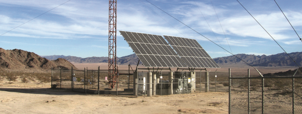
- Typical solar-telecom system architecture (high level)
A common DC-coupled architecture for an off-grid telecom site:
[ Solar PV ] → [ MPPT Charge Controller ] → [ Battery Bank (48V common) ] → [ DC Load / Inverter → AC loads ]
↑
Remote Monitoring & BMS (telemetry)
Key design decisions include nominal system voltage (12/24/48 V), whether the system is DC-coupled or AC-coupled, and where intelligence (MPPT, BMS, remote telemetry) is placed.
- Primary field challenges that drive battery choice
When designing telecom batteries for solar systems, consider real world constraints:
- Irregular solar resource — batteries must tolerate frequent shallow cycles and occasional deep cycles.
- Temperature extremes — performance and lifetime are highly temperature dependent.
- Limited maintenance access — prefer low-maintenance chemistries and remote telemetry.
- Space and weight limitations — tower shelters and rooftop sites often dictate high energy density.
- Safety and certifications — site safety requirements and transport/regulatory constraints matter.
These operational realities often make lifecycle cost and reliability more important than lowest upfront price.
- Comparing battery chemistries for solar-telecom sites
| Chemistry | Pros | Cons | Typical fit |
| Lead-acid (VRLA) | Low initial cost, proven | Shorter cycle life, heavy, maintenance | Temporary/low-load sites |
| Gel/AGM | Better temp tolerance vs flooded | Lower energy density | Medium-term deployments |
| Lithium-iron-phosphate (LiFePO₄) | Long cycle life, deep DoD, high efficiency, light | Higher initial cost | Off-grid telecom, long service intervals |
| High-energy NMC variants | Higher energy density | Thermal management & lifecycle tradeoffs | Space-constrained sites with careful thermal design |
For most modern solar-telecom deployments, LiFePO₄ (and other telecom-specific lithium packs) deliver the best blend of reliability, usable capacity, and total cost of ownership. For product-level solutions, consider dedicated telecom packs built to telecom form factors and with integrated BMS: see lithium ion battery for telecom towers.
- Sizing a battery bank — a practical worked example
Designers must size batteries to meet energy needs for a chosen autonomy (days of no solar). Below is a careful, step-by-step calculation.
Given: average continuous DC load = 300 W
Assume: 2 days autonomy, system nominal voltage = 48 V, usable DoD = 80% (0.8), system round-trip / inverter losses = 10% (efficiency = 0.90)
- Calculate daily energy demand (Wh/day):
300 W × 24 hours = 7,200 Wh/day. - Multiply by autonomy days:
7,200 Wh/day × 2 days = 14,400 Wh required energy. - Account for system inefficiency (divide by efficiency):
14,400 Wh ÷ 0.90 = 16,000 Wh (approx). - Convert required Wh to ampere-hours at 48 V:
Battery Ah = 16,000 Wh ÷ 48 V = 333.333… Ah → round to 334 Ah. - Adjust for usable DoD (if specifying nominal capacity):
Nominal Ah = 334 Ah ÷ 0.8 = 417.5 Ah → select a 48 V × 420 Ah nominal battery bank.
This shows the explicit steps you should document for procurement and site validation. Change the inputs (load, days autonomy, DoD) to reflect your particular site.
- BMS, telemetry and remote operations
Robust remote monitoring is non-negotiable for distributed telecom fleets. A proper BMS should provide:
- Cell and string voltage monitoring.
- Temperature sensing and active thermal management triggers.
- State-of-charge (SoC) and state-of-health (SoH) estimation.
- Remote alarms, firmware updates, and integration with NMS/EMS via standard protocols (SNMP, MQTT).
A battery pack without reliable telemetry is high cost in maintenance visits and surprises.
- Thermal and environmental protection
Thermal management extends life. Avoid designs that leave packs exposed to direct sunlight or wide temperature swings. Typical approaches:
- Insulated, ventilated enclosures with shading.
- Passive or active heating for cold climates (preventing low-temp damage).
- Consider derating at high ambient temps and specify vendor-tested performance curves.
- Maintenance, lifecycle cost and ROI
Although lithium systems have higher upfront cost, total cost over time (TCO) often favors lithium because of longer life, fewer site visits, and lower replacement frequency. Evaluate:
- Cycle life (e.g., 3,000+ cycles at 80% DoD for telecom-grade LiFePO₄).
- O&M costs (remote updates, fewer truck rolls).
- Generator savings (reduced runtime).
Create a simple TCO model for each site comparing initial CAPEX + 10 years OPEX under realistic site usage.
- Deployment checklist (practical)
Before procurement, verify:
- Site energy audit and daily load profile (not just peak).
- PV array sizing and shading analysis.
- Battery bank voltage and modularity plan.
- BMS and telemetry compatibility with NOC.
- Transport and installation constraints (weight, hazardous goods rules).
- Vendor test reports and certifications (UL, IEC).
- Conclusion
When designed correctly, telecom batteries for solar systems convert intermittent PV generation into predictable, resilient power that reduces operational costs and improves service availability for remote networks. Prioritize system-level thinking: right-sized batteries, integrated BMS and telemetry, thermal protection, and clear TCO comparisons. For site-ready options built specifically for telecom deployments, see the tailored product solutions at lithium ion battery for telecom towers.
Related reading